A standalone GNSS receiver can typically determine its position to within a few meters under open-sky conditions.
For everyday navigation, this is sufficient: A vehicle following a road, a pedestrian using a map application, or a fitness tracker measuring distance does not require centimeter-level accuracy.
However, a wide range of professional applications operate at a completely different level of precision. In surveying, precision agriculture, construction, and machine control, a few meters of error is not a minor inconvenience — it can mean a boundary marker placed incorrectly, a grading pass that misses its target elevation, or planting rows that overlap instead of aligning cleanly.
So how does GNSS move from meter-level positioning to centimeter-level accuracy?
The answer, for most high-precision deployments, is RTK — Real-Time Kinematic positioning.
RTK relies on a simple but powerful principle: a second GNSS receiver, installed at a precisely known location, measures many of the same errors affecting the mobile receiver and helps remove them in real time.
Where GNSS errors come from
Every GNSS position is calculated from measurements between satellites and the receiver. Those measurements, however, are affected by several distinct error sources:
- Satellite clock errors — satellites carry extremely precise clocks, but even a tiny timing error translates directly into a distance error.
- Satellite orbit errors — the broadcast position of a satellite is never perfectly accurate.
- Ionospheric delay — charged particles in the upper atmosphere slow and distort GNSS signals.
- Tropospheric delay — temperature, pressure, and humidity in the lower atmosphere affect signal propagation.
- Receiver clock errors — the receiver’s clock is far less precise than the atomic clocks carried onboard satellites.
- Receiver hardware delays — antennas, cables and electronics components introduce measurement biases.
- Carrier-phase ambiguity — although carrier-phase measurements are extremely precise, the receiver initially does not know the exact number of complete carrier cycles between itself and the satellite.
The challenge is that standalone GNSS positioning has no way to separate and remove these errors on its own. RTK solves this by introducing a second receiver.
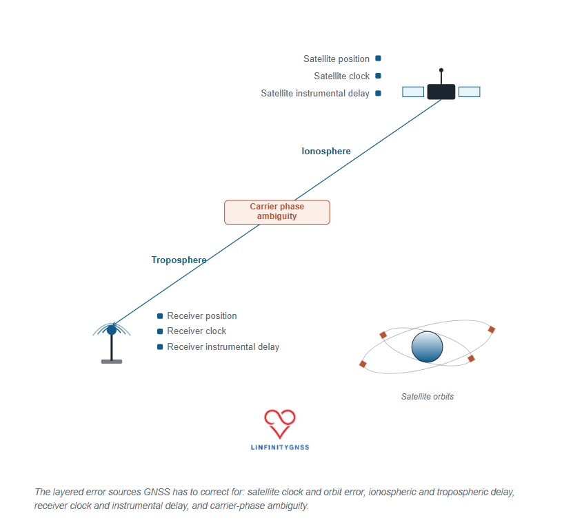
The RTK principle: two receivers observing the same errors
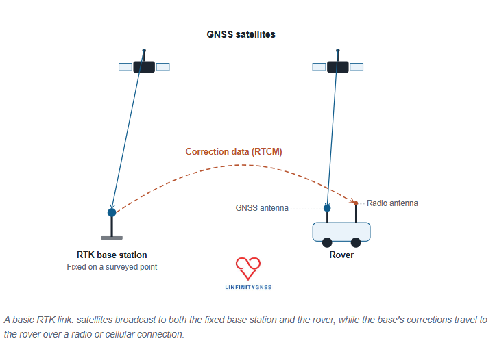
A fixed-base RTK system consists of three components:
- A base station installed on a precisely known point.
- A rover receiver whose position needs to be determined.
- A communication link carrying correction data from the base to the rover.
The key advantage of this system is that the base station already knows exactly where it is — and the rover uses this information by combining its own observations with the base’s through a two-stage process called differencing.
Single Differencing: Eliminating Satellite Errors
The first stage compares observations from the base station and the rover tracking the same satellite at the exact same time.
- What it eliminates: Satellite clock errors and satellite instrumental delay. Because these errors originate at the source of transmission, they appear identically in both receivers and cancel out completely when subtracted.
- What it reduces: Satellite orbit errors and atmospheric delays (ionospheric and tropospheric). These are heavily mitigated because both receivers look through a similar path in space, though the cancellation becomes less effective as the distance (baseline) between receivers increases.
Double Differencing: Eliminating Receiver Errors
The second stage is called double differencing where the rover’s processing engine selects one satellite as a “pivot” or reference satellite (usually the one highest in the sky with the cleanest signal).It then pairs that reference satellite with every other visible satellite individually.
- Receiver clock bias and receiver instrumental delay. Because these errors are due to the receiver’s internal hardware, they affect all satellite observations equally at that moment in time. Comparing two different satellites removes the hardware bias entirely.
What Remains to Be Solved
After this two-stage process, the remaining signal contains only three elements:
- The true geometric range difference between the two receivers and the satellites.
- A small, residual atmospheric error that grows with baseline length (limiting most RTK setups to a 20 km radius).
- The carrier-phase ambiguity, which is the unknown number of full signal wavelengths between the antennas and satellites. Resolving this final integer value is what locks in centimeter-level accuracy.
The effect of differencing can be summarized as follows:
| Error Source | Effect of RTK Differencing |
|---|---|
| Satellite clock error | “Nearly” eliminated |
| Satellite hardware bias | Eliminated |
| Receiver clock error | Eliminated |
| Receiver hardware bias | Eliminated |
| Orbit error | Strongly reduced |
| Atmospheric delay | Reduced |
| Carrier-phase ambiguity | To be resolved |
The fixed base station: the foundation of RTK accuracy
A fixed base station is a GNSS receiver installed on a stable point with accurately known coordinates. That coordinate can be obtained one of two ways.
Fixed coordinate mode
The true position of the antenna is already known, from a previous survey or reference measurement, and entered directly into the receiver — usually in Earth-Centered Earth-Fixed (ECEF) coordinates. This is the preferred approach for permanent reference stations.
Survey-in mode
The receiver determines its own position by averaging many GNSS observations over time. A short survey-in period may be sufficient for temporary setups and quick debugging, while a high-quality permanent reference station typically requires a much longer averaging period — often around 12 hours — to arrive at a stable coordinate.
Once the base coordinate is fixed, the receiver continuously compares where it knows it is against where its raw GNSS measurements suggest it is. That difference becomes the correction information sent to the rover.
Why the base antenna matters
The quality of the antenna places a practical ceiling on RTK performance. A “good” reference antenna should provide the following.
Stable installation
The antenna must not move after the coordinate has been calculated. Even a small physical shift introduces error, because the reference point is no longer where the receiver believes it is.
Excellent sky visibility
Obstructions, reflections, and multipath can contaminate measurements. An unobstructed view of the sky in every direction is essential.
Multi-constellation and multi-frequency support
Modern systems commonly track GPS, Galileo, GLONASS, BeiDou, QZSS, and SBAS across multiple frequency bands, which improves robustness and speeds up ambiguity resolution.
Good signal quality
Important antenna characteristics include right-hand circular polarization (RHCP), “suitable gain”, low-noise amplification, and resistance to interference.
The installation environment is also a very important factor — keep it clear of nearby processors, cabling, and other transmitters.
How corrections reach the rover: RTCM and NTRIP
The base station doesn’t transmit a corrected position — it sends measurement information that allows the rover to calculate its own corrected position. The industry-standard format for this information is RTCM (Radio Technical Commission for Maritime Services).
RTCM messages carry:
- Pseudorange observations
- Carrier-phase measurements
- Signal quality indicators
- Satellite information
- Antenna reference coordinates
- Ephemeris information
Modern RTK systems commonly use RTCM 3.x messages, including MSM (Multiple Signal Messages), which support multi-constellation and multi-frequency observations.
A critical practical point: the rover and base must speak the same RTCM language. A mismatch in RTCM version, MSM message type, supported constellations, or correction content is one of the most common reasons for a delayed fix or a failure to ever reach RTK FIX status.
NTRIP: delivering corrections over the internet
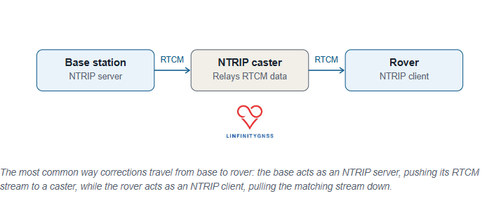
The most common way of distributing RTK corrections today is NTRIP — Networked Transport of RTCM via Internet Protocol. The architecture runs base station → NTRIP server → NTRIP caster → rover.
The base uploads its RTCM correction stream to a caster. The rover connects to that caster as an NTRIP client and requests the appropriate correction stream, usually identified by a mountpoint. This approach allows a single reference station network to support a large number of users without requiring a direct radio connection between base and rover.
The rover: where the final position is calculated
The rover is the moving receiver whose position is actually required. It needs:
- A reliable communication link
- A suitable GNSS antenna
- Compatible correction data
- Sufficient satellite visibility
Cellular connectivity, especially LTE, is commonly used for the communication link, since it offers wide coverage and sufficient bandwidth for the correction stream.
The rover continuously evaluates the incoming correction data and attempts to resolve the carrier-phase ambiguities. Its output normally includes a positioning status:
- RTK FIX — integer ambiguities successfully resolved; centimeter-level accuracy is achievable.
- RTK FLOAT — ambiguity resolution hasn’t completed; accuracy is typically at the decimeter level or worse.
When troubleshooting RTK performance, this status is usually the first thing to check.
The baseline limitation: why distance matters
Fixed-base RTK has a fundamental limitation: the distance between base and rover. The farther apart they are, the less similar their error environment becomes. A rover 5 km from the base observes almost the same atmosphere as the base does. A rover 100 km away does not.
As the baseline increases, atmospheric errors become less correlated, ambiguity resolution becomes harder, and accuracy gradually decreases. A common operational guideline keeps the rover within roughly 20 km of the base for reliable traditional RTK.
For larger coverage areas, correction networks use approaches such as a Virtual Reference Station (VRS). Instead of relying on one distant physical base, the network combines several reference stations and synthesizes a virtual reference point close to the rover — reducing atmospheric differences and improving fix reliability.
Common RTK problems and causes
The receiver stays in FLOAT mode
Common causes: incompatible RTCM messages, insufficient satellite visibility, multipath, poor signal quality, or an excessive baseline distance.
No fix despite an apparently correct configuration
Check the antenna installation, nearby interference sources, correction stream availability, and satellite tracking quality. Carrier-to-noise ratio is an important indicator — poor signal quality can prevent reliable ambiguity resolution even when the rest of the setup looks correct.
Fix degrades during movement
Possible causes: cycle slips, high dynamics, interruptions in the correction stream, or a baseline that’s simply too long.
Frequently asked questions
How many satellites are required for RTK?
The exact requirement depends on the receiver and configuration, but a greater number of satellites across multiple constellations improves reliability. Modern multi-constellation receivers commonly track dozens of signals, providing much stronger redundancy than older single-constellation systems.
Do corrections need to be continuous?
For dynamic applications, continuous correction delivery is essential. Static or slow-moving applications may tolerate short interruptions, but performance depends heavily on receiver design and the surrounding environment.
Does more correction data mean higher cost?
Usually, yes. Higher-density RTCM messages provide more information but require more bandwidth. Reducing the message rate saves data but may reduce robustness, especially for a moving receiver.
The takeaway
Fixed-base RTK remains the foundation of centimeter-level GNSS positioning. The concept itself is simple: a receiver sits on a precisely known point, measures the errors affecting GNSS signals, and sends correction data to another receiver. The rover uses those corrections to resolve carrier-phase ambiguities and determine its position with centimeter-level accuracy.
The technology is mature, but reliable performance depends on getting the details right — antenna quality, reference coordinate accuracy, RTCM compatibility, communication reliability, and baseline distance.
RTK isn’t simply about receiving corrections. It’s about establishing a trustworthy relationship between two receivers — one fixed, one moving — and using that relationship to turn imperfect satellite measurements into precise, dependable positioning.